Progress of the HO Module
Links down this page:
Oct. 21, 1999 the start.
Dec. 18. 1999 the first track plan.
Jan. 15, 1000 framework.
Nov. 27, 2000 track is laid.
Feb. 27, 2001 Control panel.
July 23, 2001 Signals.
June 24, 2002 Paving.
July 28, 2002 A Tunnel.
March 16, 2003 Greenery and Scenery.
April 27, 2003 Finish "the Module".
Administration Building on another page.
I wanted to build a module of the area surrounding the administration building to scale but it is too big. It measures to be about 7 to 8 feet long and about 4 wide. Most people fit a whole railroad on a 4 x 8 sheet and this is going to be a portable module; I have to get it into and out of my mini-van. There is a limit to the practical size of a module; my limit is 4 x 6. I could go larger and make a two-piece module but I have one of those now and they have their own special inherent problems. I decided to make it one piece with maybe an out-rigger or two, but the base module would be no larger than 4 x 6.
I started altering the prototype plans to fit into my size limitations and got nowhere. Nothing would fit right and I was not sure what it would look like. I can freelance in my head and come up with all sorts of plans, but when it comes to reproducing an actual area I need something to visualize. So I backed off and went to work on the plans for the administration building. I had to work from pictures and a sheet of materials for the building, it stated the size, 35 x 60. Once I had most of the building laid out (I still don't know what the back looked like) I glued the plan to a cardboard and built a mock-up. The roofs were made by sanding blocks of foam to the correct angles.
Here are a couple shots of my mock-up. Compare them to the actual building and tell me what you think.
Mockup one and Mockup two
With the building mock-up and the East Penn standards it was easy to layout a track plan. The standards told me that I had to:
· Keep track centers at 2"
· Minimum radius is 7.5"
· All module connection points must be at the same height. This has an effect on the hills.
· At module connections, the centerline between the two tracks must be at least 6" from the edge of the module.
· And probably some other stuff I can't recall right now.
I laid out a large sheet of paper and started drawing around the administration building mock-up. Pretty soon I had something acceptable and I posted it here. It has been condensed
because I wasn't satisfied so I kept at it. By throwing away the boundaries I was able to get a track plan that was a better representation of the prototype. You can see it at the bottom of this page.
Once I had the track plan I added the borders and quickly found that the use of those outriggers must be expanded. The tunnel will be completely on an outrigger and the 44-48 line enters the outrigger at more of an angle. The connections at the other end are to East Penn specs, but I may build a couple of outriggers just to create some parallel operation.
Compare it to the prototype and please give me some feedback. I've been looking at the full size drawing of this plan for about a week now and I'm satisfied with it. It is time to start building.
As you can see I was able to keep below my 4 x 6' maximum by attaching the outriggers. This is OK with me as long as the outrigger contains no special work. (I don't know what else to call those extra little blocks appended to the module).
I mentioned hills earlier. The Mt. Washington Tunnel rose at a 6% grade that continued to the administration building then leveled off and either dropped to the 39-42 routes, went up again to the Overbrook line, or just kept rising to the 44-48 lines. Since all module connections must be at equal height from the floor I have to fake it by just making a hump in the middle of the module, the administration building will be the high point. I will also emphasize the grades with scenery and any other trick I can learn.
Before I went to the lumber store I had one more issue to work out. I'm always torn between lightness and ruggedness when building a module. I experimented with using blue foam for the entire module but it takes some creativity getting line poles to stay in place and it is not as rugged as traditional materials. My main concern though is that I'll have to hand lay the track, I don't know how that would work on a foam base. Does anyone out there have any experience hand laying track on a blue foam sub-roadbed? So my next alternative is Homasote, I like working with that stuff, it holds spikes well and is quiet. But it only comes in 1/2 " sheets and that is heavy. I want it 1/4" to reduce the weight. I know you can get homa-bed which is sliced down but that stuff is expensive and it would be a constant cut-and-fit to get the curves I need.
In Model Railroader , September 1994, page 74, a helix was made from a product called Micore 300 that has all the good properties as Homosote but is also rigid and stable. AND it is made in 1/4 " sheets. I went through the whole search routine and came to the conclusion that 1/4" Micore is not available in the Philadelphia area. I considered using just indoor plywood but it is too hard for the spikes. So it is back to Homasote. I'll trim away what is not needed to reduce weight, but it appears to be the best alternative.
I'm now ready to start building the framework, this is when things start to go wrong. Up to this point when something was not right I taped another piece of paper over it and redrew it. That is not so easy once the wood is cut. But I'm getting ahead of myself. Since I had no boundaries on my plan I had to create some, even if they were still outside the final layout. On the south end I ran the 38-42 line and Overbrook line at enough of an angle to make them standard East Penn module connections. They go off at odd angles causing the module to look like a boat, but that's ok with me. The other ends are the tunnel and 44-49 route. I marked off the module boundaries to contain all switches, additional track could be on the outriggers. At this time I wasn't concerned about the size of the outriggers.
The first step in construction was to paint both sides of the Homasote and the bottom (best side) of the plywood. I paint them white for visibility. I laid my multi-layered (that's many layers of paper with each subsequent layer containing a different modification) on the painted Homasote, leaving extra Homasote. and I used a pounce wheel to transfer the plan to the Homasote. After removing the paper I position flex track on the plan with push pins and drew along the outside of the ties with a pencil, this is my guide for laying ties later. It also gives me a better indication of the flow of the track. Here I found my first mistake. The last section I marked was the loop around the building, I should have marked it first. There are actually two radii in that loop separated by back-to-back turnouts. Well those turnouts overlapped, and not just a little either. So I got the paper plan back out and retraced the Overbrook/38-42 tracks moving them over about two inches as I adjusted the approaches to the module connections. At least I caught this soon enough to not cause a major problem.
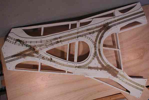
I built the frame, added a riser so there would be at least some semblance of a hill, then trimmed the Homasote and Ľ inch plywood outside the track far enough to mount the line poles. The three parts of the main module, the frame, the plywood, and the Homasote, weighed 8, 4, and 6 pounds respectively (these are inaccurate weights taken on a bathroom scale), but when glued and screwed together came to 24 pounds. That is some heavy duty glue. This made me take a hard look at the thing and brought me to the next modification, one that took a little more work.
I thought this was getting too heavy and I was not happy with the outriggers. They would make it very difficult to produce realistic scenery around the tunnel entrance and that scenery would be susceptible to damage when transporting the module. Also the 44-49 track went to the outrigger right across a corner so track cut at different angles would have to be aligned every time the module was set up, not one of my preferences. So I added a double brace across the center of the module and cut the whole thing in half. Now, with the outriggers permanently attached, the module would be transported in two pieces that were closer to each other in weight and scenery would be easier to build and more secure. An additional advantage is that only three tracks would have to be aligned during setup instead of four. One of the two, already constructed, outriggers was discarded in favor of integrated framework to gain strength and to reduce weight. These pictures show the module at this phase.
Believe it or not I'm back for an update! The track work is finally finished; all track is down and the rails gapped for the East Penn block control. We use relays wired to the spare rail to detect the presence of cars, this does a good job of preventing collisions. If you're interested you can find all about it at the EPTC Page. Since all the track is laid I suppose the track plan is finalized. Here is the final track plan for the module:
There is not much to report about laying the track; it is a slow, repetitive, process that requires great care. I used modified Orr switches and girder rail throughout. I use PC board ties in paved areas and mostly wood, with some PC board, ties in ballasted areas. I was able to use two Orr crossings but I've had to build most of them from girder rail. The same method as used in building turnouts applies; lay the curved rails first then cut and fit the straight rails. The two derails at the tunnel approach are fakes; I just soldered a piece of curved rail to the outside of the running rail then files the running rail to look like a switch tongue.
One advantage of the PC board ties is that you can cut rail gaps right over and into the tie. I always cut rail gaps over a piece of PC board, I even go so far as to solder a piece under the rail where I'm cutting the gap. I usually use a fine tooth razor saw to cut through the rail and the cladding of the PC board. If you are isolating the rails the PC board ties must also be gapped. I cut two gaps in the PC ties to make sure that a little sliver doesn't cause a short after it gets paved over.
I'm doing my best to be true to the practices of the PRCo as far as type of rail and paved and unpaved areas. I'll have T rail in those semi-paved areas and girder rail on ties where it matches the prototype. All the special work is girder rail around the junction and T rail finds its way into various places. I think I have enough pictures to justify it all.
The next step is to build line poles (I need both wood and metal poles) then start wiring and testing everything. I want to be sure I don't need to gap any more rails before I start paving over everything.
I'm also going to stray from the East Penn standard legs for this module .
I took a detour, away from the module proper, to spend some time working on controls. In the past I always finished a module then started looking for a power supply and switches to control it. I reversed myself this time and I think it will be worth it in the long run. In order to save weight on the module and, hopefully, make maintenance easier I decided to put all power supplies, control relays, and the control panel in a separate box that will just fit under the module. The only electrical accessories that will be located on the module itself are those that can't be moved to the control box - switch machines and wires. The box will be connected to the module with cables, allowing it to be transported separately. The control panel is the top of the box. The thing is getting heavy but it only has to be picked up, with the built-in handles, and moved around, it doesn’t need to be held in the air and connected to another module. I finished it last night and all that is left is to add the connecting cable and it will be ready to use. Someday I’ll add doors to it and make it look nice. Here are a couple pictures.
I am very hard to please when it comes to line poles; they are models too! Commercial line poles are too large for metal poles and painting them brown and calling them wooden poles just doesn’t make it. I cast my own wooden poles. Metal poles I make from 5/64th piano wire that I hammer through a 1/16” hole like a nail. Over this I put three or four layers of “Special Shapes” thin wall telescoping tubing. This tubing has a .006 wall so each step of the pole only adds a scale inch or so. In trying to keep with PRCo practices in pole placement I had to make about 50 of these metal poles and five or six wood poles are in the works. As you can see most of them are planted and I’m ready to add span wires. Once that is done it shouldn’t take too long to make it operational since the control panel is just about ready.
The first outing of the South Hills Junction module was very much a success. For the most part everything worked. All the relay control blocks worked as planned and I was not responsible for very many collisions. I found one track problem with a turnout that I was able to repair. The amazing thing is that the overhead worked very well. There were a few problem areas, some I was able to repair at the Meet and others I'll fix at home. I discovered the need for several additional line poles so the overhead can be properly held in position. I also have to add a couple on/off switched to better control traffic flow. The worst problem I discovered was a result of my construction habits. When I made the outriggers permanent pieces of the module I was not careful to assure that everything was flat and level. The end of one outrigger was twisted, throwing off the alignment of the other module connections. I've since done surgery on the culprit by removing the plywood from the 1x3 and inserting a wedge, raising one edge enough to level the module connection.
I added the interlocking signals to the module using three N scale three-position signals that I had. These came mounted on brass masts that I removed from two of the signals, then I remounted the signals to the line poles next to the derails. The only change I made to the third signal was the addition of an HO sized ladder, it is placed next to the first outbound switch. This picture is not the best but you can get the idea, compare to the prototype. The HO poles are still bulky looking. Dwarf signals, like these shown on Dave's were mounted to show permission for exiting the module. These I made from Tomar HO dwarf signals, I filed down the base and mounted them on a block of "concrete" wood. All the signals were wired through the relays that control the respective blocks. At least the red and green signals are done that way, the yellow is supposed to light when the derail is in the process of going to clear, only a second or two. The method of block control we use at East Penn includes a capacitor across the relay to prevent the relay from chattering. I tried to make use of this capacitor to illuminate the yellow signal but it didn’t work. I will probably have to add a couple more relays for this purpose, but that is a long way off into the future.
With the signals in place the module was ready to pave around the Administration building, add earthen ballast down toward the shop area, and ballast the other right of way. But where does the paving end, I needed the building positioned, more specifically the building base.But before the base must come the building, so if you follow this link you’ll see how I constructed it.
With the signals in place the module was ready to pave around the Administration building, add earthen ballast down toward the shop area, and ballast the other right of way. But where does the paving end, I needed the building positioned, more specifically the building base.But before the base must come the building, so if you follow this link you’ll see how I constructed it.
I’m convinced that the longest part of model building is constructing structures. It is hard to believe it has taken me since the last update to get the Administration Building to the point where I could fit the base to the module. As soon as the base was ready I went back to the module (work now progresses on both the building and module in parallel, depending on my mood), to locate that exact spot where it would look like it belonged. On to that spot I had to make a small flat level sub-base to sit it in. You’ll remember the center of the module is a big hole and the module splits right through the building. The goal is to create a base that looked like the top step into the building with no ugly gap between steps. To do this I made the base of Ľ” Plexiglas, the sub-base is plywood. Then I made the lower steps of styrene and cemented them to the sub-base using the base as a guide. The base sits down into the lower steps and the little gap that is present is not visible looking straight onto the building. The sub-base and lower steps were built as a unit spanning the two module pieces. They were then cut through with a fine saw. Here is what it looks like.
Now the area to be paved and cobblestoned were defined. I filled in some empty areas with blue foam, pulled up the pole bottoms so they wouldn’t get buried, taped over switch points, and started mixing the paving material. Modeling friends Paul Vasssallo and Gery Reighn got me started using spackling compound for paved areas. It comes in a tub, premixed to a paste, is easy to work with, and dries slowly. The disadvantage is that it is soft and can be easily damaged. After some experimenting I found that the compound can be colored with acrylic artist paint (the stuff that comes in a tube) and it doesn’t fade much when it dries, especially black. One really nice feature of this material is a trick that plasterers use; a wet sponge can be used to sand it. This gives an extremely smooth finish with no dust with the added benefit that dips and holes get filled in during the “sanding”.
I scooped out enough spackling compound to cover all asphalt areas and started mixing black into it until it was just a little darker than the end product should be. I paved around the building and the little road that came down from Warrington Ave. and across the back of the building. I also put in one walking path going up the Hollow, I will add the other path later so Bob Schmidt can get home. I make custom putty knives from pieces of plastic that fit the areas being paved. I paved everything in two coats to avoid the cracking that comes when it is too thick. The hardest part was running up the steps, the building is on a grade and while the front corner has three steps they become buried in the asphalt as you move away from that corner.
For cobblestone I used a casting method similar to what you’ve seen for making rocks. I started with a sheet of vinyl cobblestone and poured several RTV images from it. I cut the RTV molds to fit the shape of the area to be paved and mixed up so Rock Hard Water Putty darkened with acrylic paint.
The area going toward the shops and part of the back-track appeared to be earth, maybe with shale or something mixed in because some photos show it to be black. This stuff came to about the bottom of the rail head. Company trucks could negotiate it but private vehicles would be discouraged, it would be almost as bad as driving near the tracks on cobblestone. I used a combination of materials here; first I applied a thin coat of brownish colored spackling compound (it didn’t color as well as the black). Once dried and cleaned up I applied a latex-paint/water putty/walnut shells mixture. I was the recipient of a large bag of ground walnut shells, used for sandblasting, that has a very good texture and color for earth. I mixed this 5-1 with Durham’s Rock Hard Water Putty. I also have a can of earth colored latex paint that I thinned 1-3 with water. I mix these together until I get a consistency good for working between the rails. On top of the mixture I spread more ground shells then swept off the excess when dry. Take a look. I’ve seen many paved areas where rail spikes rusted and sent rust spots to the pavement as it set. Determined to avoid these nasty little marks I painted all my spikes with a touch of black rust-o-leum paint. I have none, zero, rust marks on my pavement, but I do have these BLACK spots all over the earthen areas. Sometimes you can’t win. There is a solution though, remember I said that some photos show the area to be almost black, well I’ll just follow that leas and spread on some black wash until the spots blend in.
I used the ground walnut shells because I had them and they work. There are other things that can be used as dirt, including dirt.I read somewhere that the best way to get earth colored like the real thing in your area is to use the real thing, and the best place to get it is from around home plate on a well used baseball diamond. The dirt is clean and well ground. I had a bag full of the real stuff that I sifted through an old stocking (panty hose). It made fine looking dirt. Like I said I used the shells because I had them, and I haven’t been to home plate for a while.
I finished the track work by ballasting the Knoxville and Overbrook lines and the tunnel approach. I followed well-established ballasting techniques; spread the ballast, spray it heavily with rubbing alcohol, then drip Matte Medium on it. The only unique, I think, thing I did was the weeds. Most photos of the junction area show lots of weeds in the track and I wanted to model them. I didn't like the results I get when I add the weeds to the finished ballast, and I have never been able to add weeds to loose ballast. So I decided to start with the weeds; this can be a long laborious process, gluing individual weeds between ties with white glue, but then again it fits with the overall process of building this module. I had to pull apart tiny pieces of ground cover, foliage, and trees and glue them in place, then I followed the standard method of applying ballast.
I was on vacation from work the last two weeks with nowhere to go and my goal, besides completing the honey-do list, was to make the hills on the module, including the tunnel. They are still pink and blue, but I accomplished that goal. This is also done in a straightforward manner. I just layer the 1" foam strips, trying to get the correct contour as I go. 3M 777 spray contact cement is used whenever layers are put together, it bonds instantly making it much, much faster than other gluing methods. The tunnel is essentially a foam box with Holgate and Reynolds brick for the face and liner. I used a double track stone tunnel entrance on the north end and covered that flat end with rock castings. Remember, that end of the tunnel enters a sheer rock cliff. Instead of the usual Hydrocal rock castings I half filled some commercial molds with Micro Mark 600 casting resin and rolled it around until it started to set. This gave me thin, super-light, flexible rocks guaranteed not to break when the module gets treated roughly. Just be careful to use a good releasing agent or both the mold and the castings will get ruined -- trust me, I know.
I took a semi-break from module building to put together a couple steeple cab engines. Like this project it got very involved and took much longer than expected. Maybe they'll show up in here one of these days.
As shown above I had the hills roughed out in pink foam last summer. Since then I added the ground covers using Dave Faray's water-soluble method. I applied most of the scenery at the workbench, before attaching the foam pieces to the module. There are some major advantages to this; all the mess is at the workbench, (actually a table I set up for the purpose), none of the mess is on the module or track or paving. And I didn't have any vertical surfaces to deal with; I just rolled the piece on its back. There are 5 sections of scenery, the tunnel, the hill to the school, two sections of the ridge to the west side and one small section on the east side. I first applied rocks then added layers of scenery. The trees will wait until everything is installed on the module.
During all this it became necessary to build the three staircases, I figured it would be easier to fit the ground to the stairs then the stairs to an un-conforming hill. I built the stairs from two Central Valley stairs cemented side by side. I added railings and platforms to complete the job. Then I cut and scraped at the hills to get a good fit. You can see the stairs in a couple of the photos.
I am trying to assure that everything is correct in one section before taking then next step. So before attaching any scenery permanently I tightened up the overhead, made sure (as sure as I can) that it all works correctly, then wrapped the wire neatly and cut off the excess. If you ever saw my overhead in operation you know it was hard for me to trim back the excess. Once that was done it was time to fasten the scenery to the module. But I'm still being overcautious.
I have two problems with the tunnel. First I know that someday I'll have to remove it for some reason that I can't conceive of right now. Second when a car gets stuck in there I cannot reach it, the overhead is in the way. To resolve the first problem I did not cement the tunnel to the module, I attached with large wire wraps with slices of milk bottles protecting the foam. These can be seen at the bottom of the picture. Access to the tunnel was accomplished by cutting an access door in the side. The side of the tunnel liner comes out with the access door.
The next section to be attached was the large hill. Here I am positioning it, you would be surprised at how much final fitting is required even though it was perfectly constructed in the first place. I used Sculptamold to fill the gap between the hill and the tunnel pieces, then sceniced it like the rest of the sections. Only now I have a vertical surfaces to "blow" ground foam onto. Today I added ground foam to the joint line at the bottom of these sections, I don't want anyone to see where the scenery section is attached. I won't attach the sections across the track until I am done with everything at the base of the hill, it would just make things harder.
I was right, once the hills to the left of the tunnel entrance were put in place it became very difficult to reach down into the ravine to even clean the track. I think I may have avoided a future problem by making a semi-permanent mounting. Like the tunnel section I used large wire-wraps to hold the hill in place, supplemented by a couple globs of Liquid Nails to keep if from shifting if bumped. I managed to get some scenery along the joint using Sculptamold and a lot of foliage material. Finally I fixed the stairs in place so patrons have a way to get down to the junction.
With the building finished and all the base scenery in place I am about ready to declare victory. While it will never be finished, all that is left now are details. So instead of continuing this treatise I'll send you off to a picture page that I will update periodically as the details get added.
Thanks for your attention; I just hope that someone out there is able to benefit from something I described on this page.