Wednesday, June 12, 2002
To me this is the focal point of the module and therefore it has to be right. Like I mentioned earlier I could not locate plans for the building, all I had to go was the track plan (map), a bill of materials from the original building, and a bunch of pictures. After pouring over this information for what seemed to be a long time I finally figured out the building configuration and size. I drew my own plans and built a mock-up .Then I found some styrene brick and roof sheets from Colorado Scale Models that appear to be very close to scale so I was ready to lay out the building, or was I?
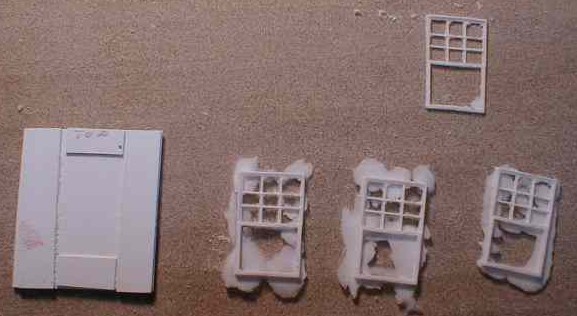
I couldn't do anything until I had the windows correct, what size were all these windows? I went back to the pictures and determined that there are four different sizes, the tops have mullions with four pains across and three down. The next step was to search for matching windows - right, sure, no problem... There is nothing even close in size and the mullions made it impossible. So I cobbled up some Grant Line windows and put them back together the way I wanted, one for each size. These are my patterns and I made rubber molds from them using Micro-Mark one-to-one RTV product. From these I cast all the windows I needed, again from Micro-Mark CR600 resin.
I made my pattern extra deep so the castings come out of the rubber mold thicker than the finished product. Then, using the styrene jig, shown on the left, to both hold the casting and measure the correct thickness, I sand the excess from the back. The three windows at the bottom are straight out of the mold, the top window has been sanded and only needs a little trimming. I now have windows and I'm really ready to lay out the walls.
Colorado Model Structures makes a very fine brick material, the bricks measure 2-5/8 x 7-7/8 and the spacing is also accurate. But there is a trade-off; this material is as tough as styrene can be. The score and snap method just doesn’t work here. It does stand up to a controlled power saw without melting, so the toughness has an advantage. This material just requires a little more work cutting and filing, but the results are worth it.

For most cuts I scored the walls and made a few cuts with a razor or model knife, then I finished it off with a razor saw. Window openings required a little extra and I found a nibbler tool like Radio Shack sells worked well for getting close to the score line.

Since I Don't have a tilting table saw I had to sand 45-degree angles into the corners. Clamping the wall sections to a piece of angle to hold them at the proper angle while sanding was a great help.

Here are all the walls and windows for the building. No, there are not six walls, two of them are offset with the first floor out at the edge of the lower roof like an enclosed porch.
Before assembling I like to paint as much as I can. The windows got a dark green spray and I mixed up a wash of earth color for the mortar. I brush on the mortar then wipe it off the tops of the brick surface. Of course it doesn't all come off giving the bricks some variation and removing the plastic sheen. Since the windows are recessed into the brick opening I gave the openings a light spray of grimy black from the back to take away the sheen there.

Windows are cemented into the openings from the back. To get a consistent recess I cut a piece of .020 styrene, seen in the right opening, to serve as a spacer.

Windowsills and caps were just 2 x 8 strips of styrene cut to length and painted white. The hardest part of this operation was determining which side of the strip was painted. I guess I'm saying the paint was not really necessary.
I do as much as possible on the flat walls before assembling into a box.

It was easiest to start assembly with the second floor. Since I didn't know how I would lay out the interior walls I just made triangular gussets to brace the outside walls. Both the floor and gussets are .030 styrene because that is what I have on hand, they should both be heavier. Use Tenax 7R, or something stronger, to penetrate the Colorado plastic. When these short walls were installed I cemented gussets to both the top and bottom of the floor, then turned it upside down and cemented the tall walls in place. This aligned the tops of all walls.

Since everything emanated from the second floor, I had to make the brackets shown above to hold the lower, short, walls. After squaring them up with aluminum angle I cemented them in place with Tenax 7R also. Adding the bay to the far corner and a short angles pieces for the back door at the near corner completed the basic shape of the building.
The base.

Knowing that the porch would project an additional 10', I now had the exact size of the building, therefore I could lay out an accurate base. When it comes to measuring things I invariably screw up, so I don't like to leave things to chance. Had I cut out a base from original measurements something would have been off and a second base would have been order. So I carefully measured it from the building, twice. The base is simply a rectangle of 1/4" plexiglas cut to fit and drilled part way through for the porch roof support posts. I used the 1/4" plexiglas partly for rigidity and partly so it would mate to the layout (see the Module Construction page). Here it is fitted into the module.
Time to do the roof.


The top edge of the lower roof is supported all around by a 6 x 6 styrene strip below the top windowsills. It was placed to allow only an inch between the sills and the rooftop. I built up rain gutters from styrene strips. In the rear of the building these are attached to additional .080 x .156 strips to the outside of the lower walls. This supports the lower roof in this area, a heavily braced porch ceiling provides support for the gutters and roof in the front. Once the supports were in place I fitted the roof. I went through several cardboard templates to get the correct angles to the roof parts, they had to fit perfectly against the walls and there are no 90 or 45 degree angles. Five roof pieces were required; in addition to each side a short piece was fitted in the front corner. The corner of the prototype roof and porch was cut back in the 30's so I did the same. This last little piece made the final fitting much easier than it could have been had it gone to a point at the corner.
I used the same method cutting the roof that I used for the walls: measure, measure, score, score, score, razor saw. I beveled the top edge so they would fit tightly against the wall. The bottom side of the bottom edge is beveled at a sharp angle, down to about 1/16", so it lays flat on lower support and forms the rain gutter.
Still to come are the top roof and chimney as well as the posts and down spouts around the porch.
The second floor ceiling can be seen in the pictures above. It was used to keep the walls square while they were assembled, and it still serves that purpose. I cemented this to a .030 sub roof that is cut to the outside dimensions of the roof. On top of this I cemented formers that form the peak. Underneath I put scribed siding that formed the overhang being careful to keep the proper spacing from the ceiling. This sub-roof was test-fitted and strips of styrene were added around the inside edges to make the walls go where they are supposed to go. The last thing to do to the sub-roof was to build up the rain gutters like I did on the lower roof.
Building Bill-of-material: